I've been dreaming about it for years, thinking it was
really too expensive and complex for me.
I decided to prove myself wrong and build my own after
finding nice simple controler plans.
Since I'm building the lathe, I tought I could automate it
on 2 axis as well!
I elected to use this
circuit from CW Tech and chose to build it myself only for 2 axis.
I had:
aluminum case
parallel port
parallel cable
computer (pentium 233mmx, 128megs RAM, 2 x 3 gigs hard drives)
parallel port card
computer power supply
7805 Power Regulator
Heat sink for above
resistors, capacitors
cables, connectors
lock switch
I needed:
Allegro UDN5804B chips (2) (these I had to order)
1N4935CT fast switching diodes (8) (these I had to order)
4.7k resistor networks (2)
terminal blocks (4.)
3" x 5" bread board with copper stripes
stepper motors (2)
home switch NO (2)
I bought the parts and waited, then put everything together and here is
the result:
Here is a bit of a pictures story.
Make you dreams alive, it's possible!
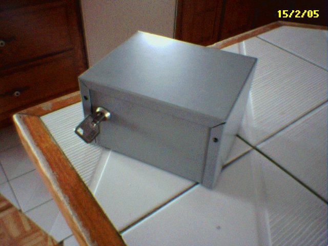
Here is a case I found. It had this hole on the face so I put this
computer lock key I salvaged.
This will keep kids and wanderers from starting this thing and breaking
it.
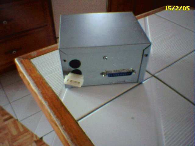
Here is the back of the box after intalling the power input and
parallel port.
Both parts come from old computers or the parts bin.
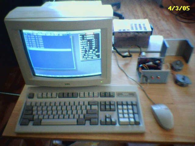
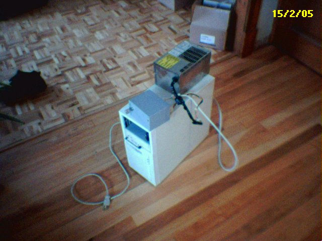
My old pentium 233mmx with 128 mb of RAM, 6 gig of hard disks, cd,
parallel port card and network.
It is pictured with my box, the power supply and the cabling. This has
not cost me a penny yet!
Plenty enough, for it's cnc purpose and sufficient for other tasks as
it will be installed in the garage
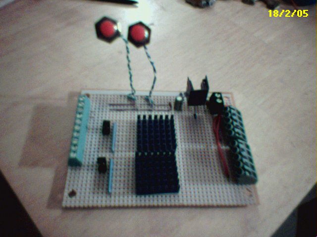
Here is the board I made. The chips and the diodes are missing but I
had to order these rare ones...
Okay, the green-gray bus is the parallel port input, the antenas are
the home switches.
At its right, the jumper bus taken from and old PC and the resistance
pack. Then the chips heat sinks.
I found those in a computer as well as the 7805 voltage controler heat
sink in the back.
The 7805 was found in a PC power supply. The numbered bus are the motor
output bus.
4 coils + common ground. The little black block behing them is the + -
power input terminals.
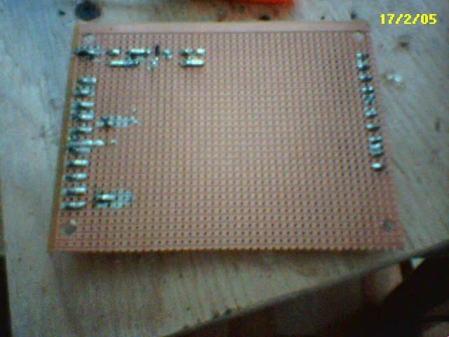
Here is the back of the board, it has strips of copper you can use and
cut to separate from other parts.
I really sucked at soldering at the beginning, been so long, but the
twist got back quick.
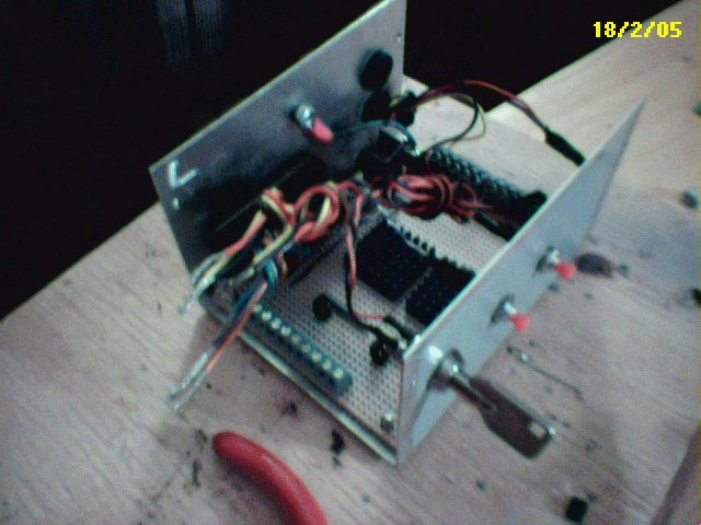
Here is the case with the board fitted. Now waiting for final seembly
at which I will add a 5A fuse.
I fitted 2 home switch on the front face of the case. The box has a
ground in the back that I will use.
The chips have arrived! Shipping and custom really killed me here... at
least double the cost!
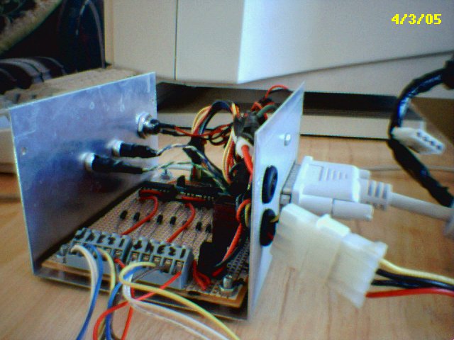
The diodes too have arrived, no problem there. So I build the thing.
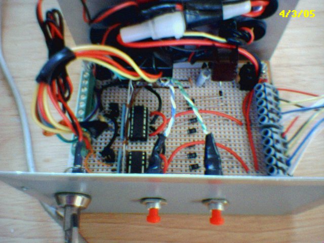
Here you can clearly see the parallel port wires and block at the left,
top is the fuse.
At the right are the motor ouput blocks, higher the power input block
and 7805 controler.
In the center are the reverse diodes and left to it the UDN5804B chips
and resistor bridge.
There are also resistors for the input circuits which you do'nt see.
And here is a story about
troubleshooting a circuit:
Here is how I made it after everything got together.
I assembled all the parts and chips
sockets, but did'nt install the chips in them, I carefully checked for
shorts between each circuits. All seemed fine. There are just so much.
Then I put some power in there... the 5 volt from the 7805 is there,
nice. So I say, let's try one chip, that one I extra that I ordered for
tests. It's in, but I check voltage on it and there is nothing...
hmmm.... so I check my circuits, geee... I forgot to solder this
wire... Here it goes, everything back in.
Now I have voltage but it's about 2 volts instead of 5v... strange, I
check the heatsink of the 7805 with my thumb and I burn myself badly...
shut the thing off, fast! So I check again for shorts, I think I migh
have got it cause the short disapeared. Again, I put everything
together and power-up the power supply. Here I have 5 volts... and the
chips is cool, the voltage controler is cool... That's cool.
Let's put a motor and the computer to it. I hook one stepper, looking
for central taps and all. Then I start turbocnc. In turbocnc, there is
an option called "ports" (F2). If you set it to Active (Alt-F2), you
can check the "pin usage" or "logic level" display (select with
Ctrl-F2) or your paralell port and look at you INPUT ports receiving
data and if set-high or low.
But I wanted to know if I could run the motor. It happens that you can
also generate OUTPUT by pressin the pin number on the keyboard. Ok, so
there I press on the #6, step pin for X-axis. The type-matic of the
computer bios makes it repeat at about 40 times per seconds and there
my motors goes for a run... I press the #2 key for direction and again
the #6 and it goes the other way! As Tim
(abymc.com) would say, W00T!!!!
Okay, so I slap the other chip in and plug the other motor the same as
previously. Again I turn the power on and try the other motor and
controler with the ports options...All of the circuitry works all
right, the motors turn and change direction and heat just a bit. When
they are power locked, it's a pretty stiff stance!
I make myself some simple g-code to test
it and launch it... nothing... So again I go in the options, reverse
the pins for step and direction for the X and Y axis, and try this...
Now I have 2 nice vibrators but that's all... Okay, I turn down the
frequency thrown at the motors down at max 300HZ since these are cheap
motors (3$) and try again.
It works! IT WORKS! This was
a blast to see both motors go in sync. The
motors have a nice little torque which should prove adequate for the
gingery lathe. I made it all for around 50$ CAN and a big dig in my bin
parts.
The motors are yet to be mounted on the yet to be finished lathe but
it's getting there. When the sand will stop freezing, and the sand will
be good working, the lathe will get alive.